

Last updated on May 19th, 2016 at 08:06 pm This example describes a two input 4-bit adder/subtractor design in VHDL.. In case of a full adder we can implement it using two half adders and one OR gate.
Module MultiStages ( input [ 3: 0 ] a, input [ 3: 0 ] b, output [ 3: 0 ] sum, output carry ); wire cin; assign cin = 1'b0; SingleStage s0 (.. One is functional, as illustrated in the next subsection Next is a logical description, where we express the outputs in terms of their logical equation.. It will contain the full-adder for 2 bits • Define the ports as follows: • a, input • b, input • cin, input • s, output • cout, output We now have several options to define this adder.. The serial binary adder or bit-serial adder is a digital circuit that performs binary addition bit by bit.
APC UPS Descarga De Software De Diagnóstico Para Mac
The final is a gate level description Pick the one that seem most interesting to you.. VHDL Code for 4-bit Adder / Subtractor -- FULL ADDER library ieee; use ieee std_logic_1164.. Let's call it FourBitAdder • Once the Project is created, add a New Source, of type Verilog Module.. Verilog Code For Serial Adder Subtractor Serial adder verilog code for Call it SingleStage.. They should all yield the same result in the next section, where we test them Functional Description of Full Adder. Winx Ripper For Mac
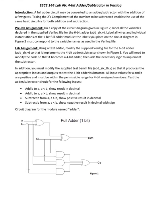
all; entity Full_Adder is port( X, Y, Cin: in std_logic; sum, Cout: out std_logic); end Full_Adder; architecture bhv of Full_Adder is begin sum.. The design unit multiplexes add and subtract operations with an OP input 0 input produce adder output and 1 input produce subtractor output.. The serial full adder has three single-bit inputs for the numbers to be added and the carry in.. The figure below illustrates the circuit: New Project • The first task is start the Xilinx ISE and create a New Project. Zt2 S Packs
in_y (carry_in ), out_sum (sum_out ), out_carry (w_carry2 ) ); endmodule Contents • • • • • • • • • • • • • • • Full-Adder in Verilog Review A full adder is a combinational logic that takes 3 bits, a, b, and carry-in, and outputs their sum, in the form of two bits, carry-out, and sum.. Click here for half-adder rtl half_adder u1_half_adder ( in_x (in_x ), in_y (in_y ),.. ~ Desktop FCD temp temp v txt html // Full Adder rtl module full_adder (in_x, in_y, carry_in, sum_out, carry_out ); input in_x; input in_y; input carry_in; output sum_out; output carry_out; wire w_sum1; wire w_carry1; wire w_carry2; assign carry_out = w_carry1| w_carry2; // Instantiate two half-adders to make the circuit.. out_sum (w_sum1 ), out_carry (w_carry1 ) ); half_adder u2_half_adder ( in_x (w_sum1 ),.. There are two single-bit outputs for the sum and carry out The carry-in signal is the previously calculated carry-out signal. 34bbb28f04 Best Rom Player For Mac
34bbb28f04
0